Sunday, 6 January 2019

Defender 300tdi Lucas 10AS Alarm Immobiliser (Spider) Problems

We have a 1997 Landrover Defender 300tdi that has given immobiliser problems intermittently. I had initially fixed the fuel solenoid as we would occasionally just come to a stop in the middle of the road , often at the most inopportune time! We could still get stranded though when the immobilser would not mobilise.

I would get mobile again by using a length of wire from the +ve of the battery under the front passenger seat to the solenoid coil terminal to start the engine. The pain was I had to remove the rubber air pipe on the diesel turbo air inlet to access the solenoid terminals. Anyway this was at least a way of starting the Defender , I had to fix this problem.

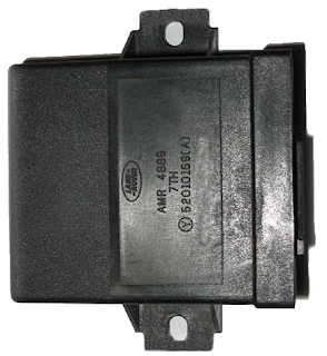
Looking on the forums for Defenders many problems with immobiliser could be traced to what was called a spider located in front of the battery under the front passenger seat. It's basically a metal box and metal lid pop riveted together with a plastic box inside that has a 12 way connector , see photo below. I took this plastic box and opened it , a PCB (printed circuit board) was inside with quite a few resistors , diodes , capacitors , an IC and two relays.

The so called Spider


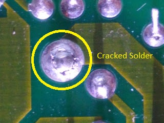
I inspected the board solder joints and the flow soldering was not very good , the solder was very dull not nice and shiny like it should be. The soldering on the relays was the worst and there appeared to be cracks round the relay main pins. I think the flow solder was not hot enough or the speed was too high through the flow solder machine when this board was manufactured. It did not wet the metal frame pins of the relays because they wicked away the heat causing poor solder connections. See the photos below showing two different cracks in the solder on two larger solder pads. Over the years the cracks grew due to temperature variations and vibrations and made the immobiliser very intermittent.



To fix this I re-soldered the whole board , every single connection , using a nice hot 350 DegC temperature controlled soldering iron. The solder joints were now nice and shiny and no cracks in the joints. I then cleaned the flux left on the board after the soldering by using IPA (isopropol alcohol). I tested the repair and the Defender started first time , before it wouldn't. This looks like the problem has been fixed. With the board like new it was refitted into its plastic box , cable plugged in and then fitted into the metal box. This metal box was then installed in its proper place under the passenger seat. Hope this helps someone with similar problems. Remember you are responsible for your own safety if attempting repairs of this nature. Job done!

Wednesday, 30 May 2018

CNC 6040 Spindle Control

Note: This is only an on - off control there is no speed control due to limitations on the CNC control box , you set the speed using the potentiometer on the VFD (Variable Frequency Drive). To be able to control the spindle connected to the NowForever VFD Spindle drive , the following is required. The Parallel port pin used was P1 deduced from the YooCNC PCB silk-screen markings RLY - P1 , this pin controls the Relay on this board. The contacts of this relay were wired in to the terminals X1 and COM on the NowForever VFD , see photos below. The LinuxCNC settings were in Stepper Configuration Wizard -> Parallel Port Setup -> Outputs (PC to Mill) Pin 1: Spindle ON , this enables the control of the spindle. The Spindle on and off buttons will now work on the LinuxCNC Axis GUI.

The G Codes required for turning on the spindle are
M3 S1 

then delay 5 Seconds to allow spindle spin up
G4 P5.0 

and for turning spindle off.
M3 S0

For milling PCBs I added these g codes to the software FlatCAM Options Tab.

Prepend to G Code
M3 S1 
G4 P5.0

and Append to G Code
M3 S0

This then means when the G Code is generated from my PCB design at the beginning of the job the spindle will spin up wait 5.0 Seconds start milling and finally will stop the Spindle at the end of the job. This hopefully will reduce the wear on the spindle by only having it on when it is doing some milling.


Thursday, 11 January 2018

BT Infinity Finally!

I have finally received super-fast broadband and it was enabled on Wednesday morning around 10am. I never noticed till a day later when I looked at my MRTG speed graphs and noticed the upload had risen from 1Mbps to 13Mbps!!! The download speed stayed at the usual just below 15Mbps but this is because the MRTG graphing only uses the last valid number when in fact the reading actually goes off-scale. I re-tuned the Download speed graph value to 60Mbps and it looks sensible now.

So my surmising what the AIO pavement spray painting meant ie signifying the installation of a all-in-one FTTC was correct. This post may also give someone whose internet comes from a far away cabinet the comfort that they may eventually get a cabinet closer to their home like in my case , I was originally connected to a cabinet ~1.5km away then moved to a new cabinet that is only 600m away.


Below shows the now stablised modem negotiated speeds , you can see a little step increase in downstream speed about midway on the graph and this may be down to a period of line speed training.


I have also been graphing actual measured download/upload speeds to various servers around the country , chosen at random every fifteen minutes or so. On the graph below you can see a baseline roughly between 30Mbps and 35Mbps for download speed , the upload speed is around 8Mbps most of the time.


I have also noticed the gradual increase in Download speeds , this seems to be done in steps , as seen in the graph I recorded.

Wednesday, 18 October 2017

File resolv.conf changed on reboot

The file /etc/resolv.conf was being reset and losing the correct nameserver on my Raspberry Pi after a reboot. The unfriendly way of fixing this was to set the immutable flag of the file using :-
sudo chattr -i /etc/resolv.conf 
It worked but I know this isn't the correct way to do it , but hey-ho life's too short....

Tuesday, 26 September 2017

Broken Ubuntu Mate Desktop

I had Ubuntu 16.04 LTS installed as a guest on a Windows 10 OS. The VM was shutdown uncleanly and after that its Mate Desktop wouldn't run properly. I re-installed the MATE Desktop using the following command.
apt-get install ubuntu-mate-desktop --reinstall 
After the re-install it worked fine with no problems. I'll remember to shutdown the VM properly next time.

Friday, 4 August 2017

Virtualbox USB Problems

Using a PC running Ubuntu with Virtualbox using Windows 10 as the guest I found I could not add usb devices using the add new usb filter. After a bit of searching I found information about the issue here.
I had to run the following command to get it to work , remember to log out and log back in after running the command.
sudo adduser $USER vboxusers
After that the add USB devices filter worked fine.

Friday, 30 June 2017

iAQ-CORE_C I²C Problems

Problems with the iAQ-CORE-C Indoor Air Quality Sensor Module. I built the module onto a breadboard pcb and while testing I found that it would not work. I couldn't detect the device on the I²C bus of the Raspberry Pi I was using. Although I could use other devices on the bus without a problem , I found a lot of forums with entries about clock stretching causing problems for the Broadcom SoC I²C bus. I even tested it on an Arduino and no data from the device was detected. After a long time checking and testing the breadboard I came across an error in my wiring that turned out to be the problem. The wire for the SDA Pin 4 was connected to NC Pin 1 on its way off the board to the Raspberry Pi. There is no mention in the manufacturers data sheet not to connect to this pin it even says not connected. I spent a fair amount of time debugging this fault and eventually got it working

Wednesday, 15 March 2017

BT Infinity in a Closer Cabinet

I have BT infinity but this gives about 15Mbps download 1Mbps upload , not very good really. The reason is I am about 1.5km from the Cabinet providing my FTTC so the attenuation in the copper and increased noise pickup causes the drop in speed. I however noticed some contractor white spray painted symbols on the pavement about 200 metres from my house with the letters A.I.O and a box shape , see my photo below.I think the AIO stands for an All In One Cabinet that BT sometimes install in outlying areas serving a smaller number of subscribers than is typical.
The main BT cable bundle that serves my house is in the duct marked BT in the picture below , so I am wondering/hoping that I will get moved from the far away one to this A.I.O cabinet? This would mean I could get true infinity speeds so I'll just have to cross my fingers and hope that this will happen. Update , got superfast broadband.

Wednesday, 25 January 2017

Getting ESPlorer to Run on Mint 17.4

I was having problems getting ESPlorer to run on my Linux machine , this to program an ESP8266 Wemos D1 Mini Clone with Lua , html content and an HA Bridge running on a Raspberry Pi for use with an Amazon Echo to control some RF remote control mains sockets. The error displayed from the console was  :-
# A fatal error has been detected by the Java Runtime Environment:
#
#  SIGSEGV (0xb) at pc=0x00007fe595a40009, pid=11774, tid=11803
#
# JRE version: OpenJDK Runtime Environment (9.0) (build 9-internal+0-2016-04-14-195246.buildd.src)
# Java VM: OpenJDK 64-Bit Server VM (9-internal+0-2016-04-14-195246.buildd.src, mixed mode, tiered, compressed oops, g1 gc, linux-amd64)
# Problematic frame:
# C  [libjava.so+0x1d009]  JNU_GetEnv+0x19
I used the command :-
sudo update-alternatives --config java  
and had the choice of either java-8-openjdk-amd64 or java-9-openjdk-amd64 on my machine. The default was java-9-openjdk-amd64 so I selected java-8-openjdk-amd64 and ESPlorer then worked without issue , I hope this helps someone in the same position.

Thursday, 18 August 2016

3D Printing PLA Not Sticking

I have found that using blue masking tape works for helping adhesion of PLA on heated build plate. Though the brand I bought was not very good in that the print wouldn't stick to the plate. 3M blue masking tape is apparently the best for this. While I waited for this tape to arrive I used hairspray sprayed onto the glass build plate , this provided good adhesion for my prints. I like the idea of the blue tape as it's less messy than the hairspray method. 

CTC Replicator 1 (Dual) Clone RFI problems

Occasionally the display on this printer becomes garbled and the reset has to be pressed. I also noticed that when this printer is on it affects the speed of my fibre to the cabinet FTTC broadband. As a licensed Radio Ham I did notice that there was little or no RFI (Radio Frequency Interference) filtering at the mains input or any ferrite sleeves over wires going to the motors and thermocouples etc. I think that the switchmode power supply is probably causing RFI to be transmitted along the mains and then it's being picked up by the telephone line so reducing the broadband speed. I will retrofit filters and ferrite's to reduce the noise made by this machine. The graph below shows the slowing effect of this printer on my broadband speed.
I have since moved my printer to another room away from the telephone line until I get it filtered better.
WARNING! modifications to your machine may damage it or cause a FIRE! you have been warned. Be CAREFUL with Hot things like your printer!

CTC Replicator 1 (Dual) Clone Printing Issues Still!

I continued to have printing issues and it took me a while to solve. I found that the filament drive stepper was clicking all of the time and had got worse over time. I had disassembled the hot-end many times but nothing seemed to help. I then compared the hot-end channel 1 with channel 0 and noticed that the heater block was loose on the hot-end feed tube on channel 0. This meant that the block was heating up ok and the temperature was reasonably accurate but the heat transfer to the hot-end was very poor. This resulted in me having to turn up the heat to around 250 DegC to get any amount of flow from the nozzle. So I tightened the feed tube onto the heat block and re-assembled everything , immediately it began to print like new again. I was able to back off the digipot values to 118 from 122 on the printer settings and no feed clicking was evident during extrusion. Happy days!
 WARNING! modifications to your machine may damage it or cause a FIRE! you have been warned. Be CAREFUL with Hot things like your printer!

Friday, 12 August 2016

CTC Replicator 1 (Dual) Clone Extruder Clicking

My CTC Replicator 1 Clone (dual extruder) which I had for a good while and had done some really nice prints , then eventually I couldn't print anything. It would feed filament in a stop start fashion usually ending in a big bundle of filament. The symptom was the right extruder stepper drive just clicked when trying to drive filament though the hot end. I dismantled the 0.4mm nozzle and heat tube and found no blockages. I then set the extruder in motion heated but without the nozzle and it was still clicking while driving. It just seemed that the stepper motor didn't have enough torque to drive the filament. I looked around the interweb and there were mentions of digipots for controlling the drive current. So I connected my laptop via USB to my 3D printer and fired up the Makerbot Desktop software and  looked at the digipot settings under Devices -> Device Settings , the setting for digipot A was 118 so I increased this to 122 ,  the maximum is 127. While I was there I changed the setting for channel B to 122 as well just in case its stepper drive had the same problem. I tried driving the filament again but nothing changed click , click , clicking Hmmm! I then pressed the reset button and this time when I drove the filament stepper there was no clicking ,  result! It appears that any changes made to the Device settings are only read in on boot so even if you change something the old value is still used until you press the system reset button whereby the settings are read in from the eeprom.
WARNING! modifications to your machine may damage it or cause a FIRE! you have been warned. Be CAREFUL with Hot things like your printer!

Friday, 5 August 2016

Makerbot on OS X Stuck in Fullscreen Mode!

I have had trouble with OS X El Capitan Version 10.11.6  and Makerbot Version 3.9.1.1143. Once you have entered fullscreen on Makerbot you will not be able to go back to the windowed version using any of the standard key combinations like esc and the ctrl + cmd + F key , it will just plain not work. To fix this from the terminal , first create a copy of /Users/your_username/.config/MakerBot/MakerWare.ini something like MakerWare.ini.orig , then edit the MakerWare.ini file using vim and look for  the WindowGeometry="..........." entry. If you remove the data after the = including the quotes " and replace it with default ( it should look like this WindowGeometry=default). Then save it , when you start Makerbot it should start back in windowed mode - hooray!!! I took ages to find out how to fix this , even forums acknowledged it was a problem but gave no solution , the fix worked , go me!

Monday, 18 May 2015

Poor Man's Through-Hole PCB Rivet

First of all I have to thank Retromaster for his descriptions on how to do through-hole contact riveting. My double-sided prototype PCBs are done on a CNC Router but originally I was using just flexible wire soldered on both sides of the PCB. This method I found just created big solder bumps , not much good for surface mount IC's with through-hole contacts directly under them. So to remedy this situation I used a drill press with a 3mm stainless rod mounted in the Chuck. I put short pieces (approx 2.6mm long = thickness of PCB 1.6mm + Protrusion on each side of PCB 0.5mm X 2  ) of tinned copper wire whose diameter  matches closely the diameter of the via hole into the via for the through-hole connection. I positioned the 3mm rod in the chuck over the via to be riveted with the copper wire in the hole and gently rotated the drill press capstan. This pressed the copper wire into the hole. I relaxed the pressure on the PCB to allow the balancing of the head size of the rivet on both sides of the PCB. Below is a photo of some practice rivets and one via not riveted on a scrap PCB for practice, these rivets will have a light soldering using solder paste to ensure a good electrical connection. I am very pleased with this method of connecting vias on PCB prototypes.

Riveted through-hole connections


Thursday, 5 March 2015

BT Infinity and my HG612 VDSL2 Modem Firmware Upgrade

Speed kbps
My Home Download Speed
Warning: If you attempt what I describe here you may reduce your modem's usability to that of a brick , remember you are in charge of your own destiny. Note: I have two modems one for experiments and the other as backup.
 
I have been in the habit of using a Raspberry PI to log my ADSL2+ then VDSL2 speeds for a while now. The graph above is the speed of my ADSL2+ until I got BT Infinity or FTTC (Fibre To The Cabinet) , the time is about a year in span and speed is in kbps. Point A is when my ADSL2+ speed a took a dive due to a tree wearing through my overhead telephone line. It took BT about a full month to fix the fault and remove the subsequent speed cap at Point B , it took two emails to the BT Community Forum to get them to remove the cap even though they said that it had been removed , it hadn't.
Between Point B and C you can see my speed was unstable with my router continually dropping connection and then re-syncing at different speeds. You can see how unstable it was even after the line repair compared with the lead up to Point A , perfect. I then had BT Infinity installed at Point C using a BT Openreach Huawei EchoLife HG612 modem with unlocked firmware. This allowed me to log speeds , it isn't something that is enabled by default with BT's stock modem.
Between Points C and D it is not very stable speed wise , I have a long wire to the cabinet hence the lower than anticipated VDSL2 speed. So eventually I got a bit fed up with the variability of the connection speed so I tried new firmware in my modem , this firmware has a newer binary blob driver for the Broadcom modem chipset. Point D shows the time the modem had the new firmware flashed , it is a higher speed and also very stable , fantastic. So the only thing that has changed is the firmware change on the HG612 at point D. This also just shows that the digital signal processing elements have been improved in this binary blob driver.  Now I'm very impressed with the latest firmware for this modem , but it's a shame I've had to do all this firmware upgrade myself and that BT don't seem to be continually improving their modem firmware. This even though they do have BTAgent enabled to update firmware themselves.
I have BTAgent disabled because I don't want them to disable my logging system with their new firmware. They seem more concerned with not allowing their customers to actually see how bad their broadband connections are by disabling useful functionality. It has been noted by others that some of the BT firmware updates rolled out via BTAgent have disabled Web Configuration and telnet access to these modems.
Hope this helps you.

Monday, 1 December 2014

Mercurial Repository Direction

I'm in the NewRepo directory in the local repository on my local machine and want to clone this to a remote repo. I had forgotten that the command order dictates the direction of the clone ie from my local to remote repo or remote to local repo
local -> remote
hg clone . ssh://user@usersURL.org/hg/myrepos/NewRepo
 remote -> local
 hg clone ssh://user@usersURL.org/hg/myrepos/NewRepo .

Sunday, 10 August 2014

LG 42LH3000 TV half picture

My LG 42" Television Model No: 42LH3000 developed an intermittent fault where the left half of the picture on the screen would become noisy and garbled , see this video.


LG 42LH3000 Television

It was worse when the TV was first switched on but got better as it warmed up. Over time it gradually got worse until no picture was shown on the left side at all. From an Internet search it seems that it is a common problem where the LCD driver transistor array die bonded to the flexi-circuit along the top of the LCD loses connection. These devices are driven by the Tcon board at the top middle of the TV via two flex-circuits, these connectors were checked for bad connection but were fine. It was later found that the flex-circuit transistor array on the far left of the LCD when pressed gently would fix the screen problem. A couple of thin cardboard spacers were cut and placed under the flexi-circuit transistor array ( I did this for all the arrays just in case the problem occurred on the remaining arrays ) to make it press more firmly against the silicon rubber pad on the removable front pressed steel bezel of the LCD. This helped ensure that the array would be pressed firmly by the silicon rubber pad when the front frame was replaced and the screws firmly tightened. I hope this helps someone with similar problems and thanks for reading.

Update: After a day the screen had the same problem. Over the course of about a month I disassembled the TV three times trying a number of rubber gasket materials including sticky draught excluder , these worked for a while each time then the screen developed the fault again. On the fourth disassembly I removed the factory fitted flexible rubber pad pushing down on the leftmost flexi-circuit at the top of the screen. I did notice that the bonded transistor array on the flexi-circuit assembly was warm to the touch when the TV was running out of its case.


Positions of Silicone Strips

So I ordered a sheet of thermally conductive silicone rubber 1.6mm thick , I cut three strips strips of this 10mm x 35mm and sandwiched two of them together. The other strip was placed carefully under the flexi-circuit transistor array die while the other two were placed on the top of the flexi-circuit transistor array die (see image above for rough positions or the rubber strips). This assembly would then be clamped once the front pressed steel frame bezel was screwed to the front LCD panel surround. After this was done the TV has worked since so I think the problem may also be related to the transistor array overheating and the thermally conductive silicone rubber is now removing the associated heat from the transistor array to the front metal bezel of the LCD panel. See the diagram for the the way the strips were positioned.

Flexi-circuit Sandwich , Looking Down from Top Edge of Screen
   

Remember that TV's have mains voltage and also higher voltages for the cold cathode strip lamps exposed when the rear cover of the TV is removed so be careful. You may by fiddling with these transistor arrays make the connection problem worse, but if the TV is already toast what have you got to lose.

Sunday, 8 June 2014

Ford Fiesta ABS Light Stays On


The ABS warning light lit up continuously on my daughters Ford Fiesta Style 2005 plate.


ABS Symbol


After a bit of Googling (other search engines are available) to see what the fault could be and narrow down my search area. I finally got around to taking each wheel off in turn and checking the wheel speed sensors for damage. I found the drivers side front wheel speed sensor's wire insulation nearest the inside of the wheel arch had worn away exposing the copper wires inside, it had also worn away one of the wires. The sensor wire wearing away may have been due to a broken suspension spring that occurred a while before the ABS fault, the spring was replaced a while back. As a test repair I soldered the broken wires of the sensor back together and switched on the ignition but the ABS light stayed on. Disappointed I drove down our private road and after driving about 30 feet the light went out, yeehaa! (this is me happy). Apparently from what I have read the ABS light will stay on even after a sensor repair until the ABS system detects pulses coming in from the sensor after the vehicle is in motion, only then will the light go out.  I ordered and fitted a new sensor cable assembly to replace the temporarily repaired one as I didn't want to take chances with a repair on the ABS system, the ABS light has stayed out ever since.
If you undertake any work, be safe, remember cars are heavy, tools are dangerous if used incorrectly, you are responsible for your own actions.
UPDATE:
I bought one of these F-Super Diagnostic USB dongles to read the fault codes and reset the fault on the ABS ECU.
F-Super Diagnostic Dongle
I installed the drivers and the software onto my laptop, plugged in the usb. I then plugged in the dongle to the OBD connector on the Fiesta, it is located at the bottom of the Steering column cover under a little flap. The software was run and the fault code read it was indeed signal loss from a wheel sensor. I wish I had this device before, so I knew what I was looking for when trying to fault find.
I also reset the fault code on the ABS ECU so if the error comes back I'll know.

Thursday, 15 May 2014

Arduino Uno Ceramic Resonator

I was using an Arduino Uno to measure the PPS (pulse per second) pin from a GPS module to allow comparison with the PPS from a DS1307 RTC real time clock. I used interrupts 0 and 1 of the Arduino to trigger on rising edges of both PPS pins to trigger a reading from the micros() function and then subtract this reading from a subsequent micros() reading taken on the next rising edge so giving me a measure of the pulse width in microseconds, give or take four microseconds. Apparently the misnamed micros() function cannot make one microsecond measurements. Using this setup I was able to see that the 16MHz clock on the Arduino was out compared to the GPS PPS pin which from the datasheet was accurate to the tens of nano seconds range. The measured error I found was due to the Arduino using a resonator for its system clock, known for not being as accurate a crystal. The strange thing is there is already a crystal on the board for the USB serial chip, probably for accurate baud rates, it is 16MHz the value we need. I removed the resonator for the ATMega328P from the board and made a direct connection from the crystal oscillator output of the USB serial chip to the oscillator input of the ATMega328P. The board can still be programmed and now has a more accurate system clock for my measurements. I wonder if this is something that could be done to the Arduino to save the cost of a resonator. I eventually moved my sketch to a Stellaris Launchpad which has an 80MHz clock and can measure down to one microsecond with its appropriately named  micros() function.

16MHz Resonator removed, center of PCB

16MHz Osc Output of ATMega8U2 connected to ATMeg328P Osc input

Defender 300tdi Lucas 10AS Alarm Immobiliser (Spider) Problems

We have a 1997 Landrover Defender 300tdi that has given immobiliser problems intermittently. I had initially fixed the fuel solenoid as we w...