Tuesday 12 November 2013

Wireless Charging on a Star S7189 Mobile Phone

Warning: while soldering be careful of solder fumes, wear eye protection and don't burn yourself.  Note that charging batteries can be dangerous especially Li-Ion but the work detailed here means we are effectively generating our own internal 5V supply in the phone and connecting this directly to the USB power connections as they come into the phone. It is the equivalent of connecting a micro USB cable to the phone from a 5V USB charger, only its wireless. You have been warned and I am not responsible for your actions.


S7189 Display

This S7189 quad-core Android phone from Star was pretty cheap around £100 and it worked well.  I found the front facing camera was not the best, but for the price I can live with it. Screen was also pretty good with a reasonable viewing angle. It was also pretty slick running any Apps I downloaded from Play with no signs of lagging.

Palm Internal Charging Circuit
I wanted to add wireless charging to the S7189 so I didn't have to keep plugging the charger into the micro USB connector. I noticed on HackaDay that some people had added wireless charging to their mobile phone , this is what I wanted. So I ordered a wireless Palm case back from Ebay for £3.

Palm Back Cover

I then using scissors cut out out the area of plastic bounded by the Plastic label with Palm on it. This was to allow one to be able to peel off the label more easily from inside the case. I then stuck the label on some plastic film (after removing the circuit board, coil and metal discs) to preserve its stickiness.  

Circuit Cut Out of Plastic Cover
The coil and circuit board were removed from the old Palm cover by soaking in a plastic tub of Methylated Spirits for a few hours to soften the double-side sticky tape holding circuit and coil onto the plastic cover.

Sticky Cover Preserved

Stuck to Clear Film


S7189 Back with Cover Removed


The S7189 internal back cover is removed (quite a few small black screws) exposing the Circuit board. I plugged in a Micro-USB adapter to find out where the center conductor was connected to on the Power PCB at the lower part of the phone using a multimeter set to continuity tone check. Ground was the metal tabs of the Micro-USB connector. I used Kapton tape to insulate the sticky copper foil I was using to route out power to the top of the back cover.

Ground Connection

I then soldered flexible tinned insulated wire between the two Copper tabs next to battery, taking care not to overheat the plastic.

Routed Copper Tape


Palm Charge Circuit Added to S7189 Back Case
The removed Palm charge circuit was stuck to the middle of the S7189 back cover using its original sticky cover. Of the two small square gold connectors to the left of the Kapton tape the Lower one is the +5V the upper one is 0V or Ground. To be sure check the output yourself with a multi-meter to ensure you have the correct polarity before connecting it to your valuable phone.


Phone Placed on Charger

Phone Now Charging


The S7189 is now able to be charged either by using the Micro-USB or wirelessly via the Palm Touchstone charger. Note: don't use both at the same time or there could be overcharging problems with subsequent overheating and fire from the battery and circuit boards.


Pure Evoke 1 Crackly Burbling Audio

Warning: while this radio is low voltage around 12V dc no mains voltage appears in the actual radio, so it is relatively safe to work on. The wall-wart power supply itself however is mains voltage ( in my case it's 230V AC ) so this needs to be treated with respect. Also while soldering be careful of solder fumes, wear eye protection and don't burn yourself. You have been warned, I am not responsible for your actions.


I have had this Pure Evoke 1 DAB radio for about 7 years but it started having problems. The audio became crackly and it also had an associated burbling noise. The signal quality displayed for the radio station I listen to normally which previously was 97 was now wavering between 40 up to about 70.
The first thing I tested was the most accessible thing the wall-wart power supply. This power supply seemed to be ok, measuring around 17.4 volts dc on my Fluke multimeter.

Evoke 1 Amplifier Board
I opened the case of the Evoke (remove all the screws on the back of the case) this is where I noticed that the antenna f connector was loose. I tightened the f connector using an adjustable spanner and pliers. Thinking it was a poor signal because of the loose connector I switched it on again but the audio problem was still present. I then proceeded to measure the regulator voltages on the main audio board. Most voltages appeared ok, however I noticed that the 3.3v supply which supplies the RF board was not solid but was wavering round quite a bit. I examined the electrolytic capacitors on the board but found no evidence of them being swollen due to localised heating from the various heat-sinks on the board.
So I started removing the capacitors on the amplifier board one-by-one to test them on my Peak capacitance and equivalent series resistance meter. All capacitors measured well within 10% of their marked values and low ESR apart from one capacitor, C7 a 100uF 16V electrolytic which is located very close to a regulator heatsink that runs very warm. Its value measured low and its ESR was higher than it should be so it appears that it is effectively being dried out over time.

Faulty Capacitor C7 on the tester
 I replaced this capacitor with one of equivalent value but its voltage rating was higher at 25V this is not a problem in this application.

When I soldered the new capacitor into the board I bent the new capacitor body away from the offending 3.3 V regulator heat-sink to prevent the new capacitor being dried out with the heat.
Capacitor bent away from heat-sink
The signal quality returned to 100 after the repair, I soak tested the radio to ensure that it was repaired.

Job done. Thanks for reading and good luck if this is what has happened to your Pure Evoke 1.

Saturday 21 September 2013

Use an ATTiny45 to auto-boot a NAS200 on power up

I make no guarantees for the information contained herein, I also cannot be held responsible for data loss as a result of your actions, we make our own decisions.

I needed a way of booting the Linksys NAS200 automatically when powered up. As standard from Linksys the NAS200 just stays off when powered up. The Power button on the back left hand side when looking at the rear of the NAS200 needs to be pressed to start the NAS. I often found that when I tried to connect to the NAS it was powered off usually due to a power outage that occurred through the night. I would then have to go upstairs to power it on and wait for it's disk check to finish before I could actually use it. So I set out to fix this inconvenient feature of the NAS200.  First power off and disconnect the power supply then remove the hard drives so they don't get damaged. I numbered the drives 1 and 2 to match the bay they came out of before removal just to be sure they went back into the correct drive bay.  I proceeded to open up the case of the NAS. This involved removing the silver painted base cover using a screwdriver to lift the plastic sprung pillars out and then slide the cover to the front of the NAS. Four screws included one covered by a warranty sticker ( 
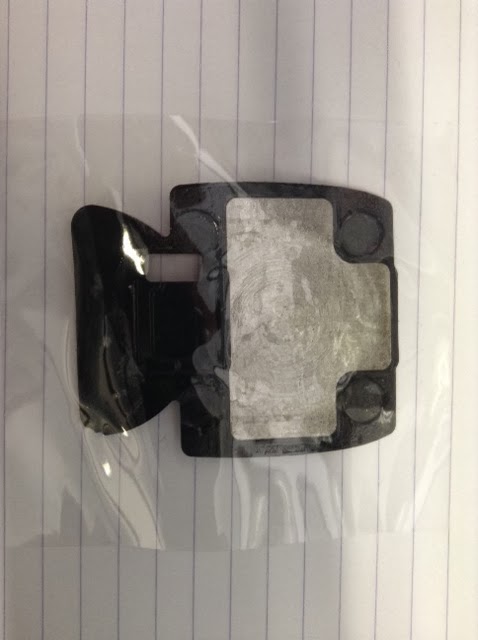
only proceed if you are happy having no warranty and only if you are confident of success ) are removed. This allowed removal of drive bay 2, be careful of the power wires to PCB and SATA connector. Another four screws are removed to remove drive bay 1, again be careful of SATA and power cables. This will allow the main PCB to be accessed. Four screws are removed and this allows the PCB to be removed. An 8 pin socket was procured, pin 4 was soldered to the rear of one of the PCB mounted USB socket, pin 8 was connected to the 5V pin on the LM7805 voltage regulator see the picture below.

NAS200 ATTiny45 in Socket

Pin 5 is connected to the conductor of the power push button at the rear of the PCB via a flexible insulated wire, I soldered it to the top of the push button.

The ATTiny45 was programmed using an Arduino Uno programmed with the ISP Sketch, it's in the Arduino IDE examples, remember to choose the correct board and serial port in the IDE. See my previous post on how to program the ATTiny45 with the Arduino Uno Board.

The AutoPowerON.ino sketch basically sets up the port pins we are using as inputs this gives us the high impedance state so the pins don't affect the NAS200 power up or switch off function using the button. After 10 seconds (just to be sure the power has settled) from power being applied the pins on the ATTiny45 being used are set as outputs and PB0 PB1 go low and high respectively for half a second. They then return to high impedance state, the NAS200 has begun booting. After this the program in the ATTiny45 is then caught in an infinite loop, this ensures the pins are only pulsed once for each power cycle.
Note* I only use pin 5 this is the active low output, pin 6 can be used for circuits that may need an active high 5V pulse.
Code I used is pasted below I saved it as AutoPowerON.ino :-

/*
 NOTE* This Sketch will pulse a Pin low on the ATiny45
 This is to auto power up a NAS box to ensure it
 is available after a power cut. It normally has to be
 turned on by pressing the power button.
 If using an Arduino to program these devices you need to 
 program the ISP Sketch found in the IDE onto the Arduino 
 first. 
 
 So the circuit will pulse a pin low after a
 predetermined amount of time say 10 Seconds
 
 This pin will be connected the same part of
 the NAS box's push button circuit to simulate
 a button press.
 We only want to do this procedure once on every power up.
 hence the capture while loop at the end of the loop function.
 
  +5V---------------------+
                       Vcc|
                     +----------+
                 PB2 |    8     |PB4
               +-----|7        3|----+
                 PB1 | ATTiny45 |PB3               
               +-----|6        2|----+             
TO               PB0 |          |PB5             
Push Button    +-----|5        1|----+          
                     |    4     |    
                     +----------+  
                       GND|          
   Ground-----------------+                          

(Wiring Diagram for Auto Power On Circuit)
 
 By Jim Park jim (dot) buzz (at) gmail (dot) com
 Coded :- 18/09/13
 
 */
 
int PowerPin = 0;          // Pin 5 to power up the NAS if it's active Low  
int PowerPinInv = 1;       // Pin 6 to power up the NAS if it's active High

void setup() {
// declare pins as O/P's or I/P's
  pinMode(PowerPin, INPUT);           // HI-Z pin
  pinMode(PowerPinInv, INPUT);        // HI-Z pin
}

void loop() {
// Now delay for 10 Seconds
  delay(10000);                       // 10 second delay to be sure power is stable
  pinMode(PowerPin, OUTPUT);          // Remove HI-Z state from pin
  pinMode(PowerPinInv, OUTPUT);       // Remove HI-Z state from pin
  digitalWrite(PowerPin, LOW);        // Active Low on Pin 5
  digitalWrite(PowerPinInv, HIGH);    // Active High on Pin 6
  delay(500);                         // Half a second delay
  pinMode(PowerPin, INPUT);           // Back into HI-Z state
  pinMode(PowerPinInv, INPUT);        // Back into HI-Z state
  while(true){}       // Capture for ever......and..ever.........
}


The programmed ATTiny45 is inserted into the socket carefully ensuring that pin 1 on the ATTiny45 goes into pin 1 on the Socket ( see the photo above ). The unit was tested by plugging in the power to the NAS, after 10 seconds the familiar boot beep with the flashing leds occurred. After the full boot the NAS was available on the network all without having to press the power button. :)

Thursday 5 September 2013

Programming ATTiny45 using an Arduino Uno

Wiring of the Programmer
The Arduino is programmed using the Arduino IDE and USB with the ArduinoISP sketch from the File Menu located in examples. Remember to choose the correct board and Serial port from the Tools menu, I was using an Uno. You have to set up the Arduino software to be able to program devices like the ATTiny45, I used the http://hlt.media.mit.edu/?p=1695 site to add the support. It was then just a matter of wiring up the Arduino as shown, putting an ATTiny45 in the 8 pin socket selecting the new board ATTiny45 (Internal 1MHz Clock) and programming the device with a sketch I wrote for this particular device.

Wednesday 4 September 2013

Wi-Spy DBx2 USB Repair

Be careful when soldering and wear eye protection. I am not responsible for any omissions or errors on this Blog YMMV.

Broken USB Connector


The USB connector had been ripped off the board ( it wasn't me :) ) so I cleaned and removed the broken lugs from the PCB. I also cleaned the PCB pads left on the USB connector.
Pulled Out Contact
I straightened one of the contacts that had been pulled out of the connector and pushed it back in. I then Fast-Set Epoxied the connector to the PCB and clamped it using a sprung plastic clamp until the glue cured. I then soldered the ground connection and the remaining connections using thin tinned copper wire to bridge the ripped up tracks on the PCB. I finally soldered the corners of the connector to the PCB lug holes to provide extra mechanical strength to the assembly.
Connections Soldered
Proof it Works!
Job Done :).

Thursday 4 April 2013

Raspberry PI Enterprise Wifi

The dongle I used was the Farnell WiPi this was identified by the PI using
the command lsusb as a
Bus 001 Device 005: ID 148f:5370 Ralink Technology, Corp. RT5370 Wireless Adapter

I put the required certificate in the /etc/cert directory.
The wpa_supplicant.conf file was edited as follows:-
ctrl_interface=DIR=/var/run/wpa_supplicant GROUP=netdev
ctrl_interface_group=root
update_config=1
network={
ssid="myAP"
key_mgmt=WPA-EAP
eap=PEAP
identity="myuser"
password="mypassword"
ca_cert="/etc/cert/cacert.crt"
phase2="auth=MSCHAPV2"
priority=0
}

The file /etc/network/interfaces was edited as follows :-
auto lo
iface lo inet loopback
iface eth0 inet dhcp
allow-hotplug wlan0
iface wlan0 inet manual
wpa-roam /etc/wpa_supplicant.conf
iface default inet dhcp
gateway 192.168.1.1
up route add default gw 192.168.1.1

Raspberry PI Kiosk

Do the usual things after installing an image on the SD card and booting the Pi
for the first time run
sudo raspi-config
then set boot desktop in boot_behaviour

sudo apt-get install chromium x11-xserver-utils unclutter

Edit /etc/xdg/lxsession/LXDE/autostart file and comment out screensaver line, add lines below
@xset s off
@xset -dpms
@xset s noblank
@chromium --kiosk --incognito http://www.google.com # your URL here


Monday 25 March 2013

Repairing a Windows Installation After Installing a New Motherboard.


The usual warnings about backing up data before you proceed apply here, you have been warned.

I needed to do this after the motherboard's hard drive controller died and I didn't just want to do a re-install and lose all my settings and accounts with a motherboard change, I did have a backup but I wanted a challenge. I rebooted with the new motherboard installed and just got the BOD then a restart. The Windows recovery came up during this reboot but in the end it said the installation couldn't be recovered.

Most of the forums I came across recommended a re-install, this I thought was a bit defeatist so a bit more research came up with a useful article:-
How To Repair a Windows Install After Replacing Motherboard
I followed this pages description and got the drivers I needed for my new motherboard. I put them on a USB memory stick then booted the new machine with the Windows 7 install DVD as described in the article, the important command is :-
dism /image:d:\ /add-driver /Driver:f:\ /recurse
This copies the various drivers for the new motherboard chipset, vga, harddrive controller and audio etc from the USB memory stick to the Windows installation on the hard drive. This means when Windows restarts it'll have all the correct drivers for the new motherboard. It did reboot and appeared to work, no BOD, it rebooted again after the initial boot. Fantastic it only took about half a hour and it works flawlessly.

Update:You may need to re-validate your copy of Windows with Microsoft as the hardware has changed significantly. I had to use Microsoft's automated UK 0800 telephone re-validation system, this was pretty painless, just enter a few blocks of numbers provided by your installation via the phone keypad. You then enter the automated-voice blocks of numbers returned by Microsoft's system into the blank boxes on your installation. All legal again :).
Thanks for reading. Best Wishes.

.........

Defender 300tdi Lucas 10AS Alarm Immobiliser (Spider) Problems

We have a 1997 Landrover Defender 300tdi that has given immobiliser problems intermittently. I had initially fixed the fuel solenoid as we w...