 |
| Riveted through-hole connections |
A place to where I can record my Technical stuff that should be accessible from anywhere. It is mainly technical stuff I find interesting and I suppose it can be looked on as a modern Lab-book.
Monday, 18 May 2015
Poor Man's Through-Hole PCB Rivet
First of all I have to thank Retromaster for his descriptions on how to do through-hole contact riveting. My double-sided prototype PCBs are done on a CNC Router but originally I was using just flexible wire soldered on both sides of the PCB. This method I found just created big solder bumps , not much good for surface mount IC's with through-hole contacts directly under them. So to remedy this situation I used a drill press with a 3mm stainless rod mounted in the Chuck. I put short pieces (approx 2.6mm long = thickness of PCB 1.6mm + Protrusion on each side of PCB 0.5mm X 2 ) of tinned copper wire whose diameter matches closely the diameter of the via hole into the via for the through-hole connection. I positioned the 3mm rod in the chuck over the via to be riveted with the copper wire in the hole and gently rotated the drill press capstan. This pressed the copper wire into the hole. I relaxed the pressure on the PCB to allow the balancing of the head size of the rivet on both sides of the PCB. Below is a photo of some practice rivets and one via not riveted on a scrap PCB for practice, these rivets will have a light soldering using solder paste to ensure a good electrical connection. I am very pleased with this method of connecting vias on PCB prototypes.
Subscribe to:
Comments (Atom)
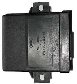
Defender 300tdi Lucas 10AS Alarm Immobiliser (Spider) Problems
We have a 1997 Landrover Defender 300tdi that has given immobiliser problems intermittently. I had initially fixed the fuel solenoid as we w...

-
Server failure This server failed with the error "E171F PCIE Fatal Err B0 D3 F0" during power up. Upon inspection it was found th...
-
I make no guarantees for the information contained herein, I also cannot be held responsible for data loss as a result of your actions, we m...
-
I bricked my MR3220 router with an OpenWRT firmware upload. I did manage to get it back by soldering a 4 pin header on its pcb to allow conn...


